


Radio Apocalypse: America’s Doomsday Rocket Radios
Even in the early days of the Cold War, it quickly became apparent that simply having hundreds or even thousands of nuclear weapons would never be a sufficient deterrent to atomic attack. For nuclear weapons to be anything other than expensive ornaments, they have to be part of an engineered system that guarantees that they’ll work when they’re called upon to do so, and only then. And more importantly, your adversaries need to know that you’ve made every effort to make sure they go boom, and that they can’t interfere with that process.
In practical terms, nuclear deterrence is all about redundancy. There can be no single point of failure anywhere along the nuclear chain of command, and every system has to have a backup with multiple backups. That’s true inside every component of the system, from the warheads that form the sharp point of the spear to the systems that control and command those weapons, and especially in the systems that relay the orders that will send the missiles and bombers on their way.
When the fateful decision to push the button is made, Cold War planners had to ensure that the message got through. Even though they had a continent-wide system of radios and telephone lines that stitched together every missile launch facility and bomber base at their disposal, planners knew how fragile all that infrastructure could be, especially during a nuclear exchange. When the message absolutely, positively has to get through, you need a way to get above all that destruction, and so they came up with the Emergency Rocket Communication System, or ERCS.
Above It All
The ERCS concept was brutally simple. In the event of receiving an Emergency Action Message (EAM) with a valid launch order, US Air Force missile launch commanders would send a copy of the EAM to a special warhead aboard their ERCS missiles. The missiles would be launched along with the other missiles in the sortie, but with flight paths to the east and west, compared to over-the-pole trajectories for the nuclear-tipped missiles. The ERCS trajectories were designed to provide line-of-sight coverage to all of Strategic Air Command’s missile fields and bomber bases in North America, and also to SAC bases in Europe. Once the third stage of the missile was at apogee, the payload would detach from the launch vehicle and start transmitting the EAM on a continuous loop over one of ten pre-programmed UHF frequencies, ensuring that all strategic assets within sight of the transmitter would get the message even if every other means of communication had failed.
ERCS mission profile schematic. From launch to impact of the AN/DRC-9 payload back on the surface would only be about 30 minutes, during which time the EAM would be transmitted to SAC forces on the ground and in the air from Western Europe to the middle of the Pacific Ocean. Source: ERCS Operation Handbook.
Even by Cold War standards, ERCS went from operational concept to fielded system in a remarkably short time. The SAC directive for what would become ERCS was published in September of 1961, and a contract was quickly awarded to Allied Signal Aerospace Communications to build the thing. In just four months, Allied had a prototype ready for testing. Granted, the design of the payload was simplified considerably by the fact that it was on a one-way trip, but still, the AN/DRC-9, as it was designated, was developed remarkably quickly.
The 875-pound (397-kg) payload, which was to be carried to the edge of space at the tip of an ICBM, contained a complete “store and forward” communications system with redundant UHF transmitters, along with everything needed to control the deployment of the package into space, to manage the thermal conditions inside the spacecraft, and to keep it on a stable trajectory after release. In addition, the entire package was hardened against the effects of electromagnetic pulse, ensuring its ability to relay launch orders no matter what.
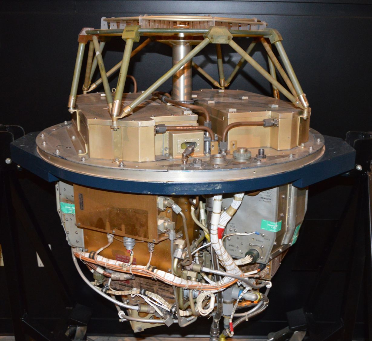
AN/DRC-9 on display at the Air Force Museum. This is mounted upside down relative to how it was mounted in the rocket; note the spiral antenna at the top, which would be pointing down toward the surface. The antenna struts are mounted to the twin zinc-silver batteries. The exciter and final amp for one of the transmitters are in the gold boxes at the lower left. Source: US Air Force.
The forward section of the package, just aft of the nose cone, mainly contained the equipment to activate the payload’s batteries. As was common in spacecraft of the day, the payload was powered by silver-zinc batteries, which were kept in a non-activated state until needed. To activate them, a gas generator in the forward section would be started about 45 seconds prior to launch. This would provide the pressure needed to force about seven liters of potassium hydroxide electrolyte solution from a reservoir in the forward section through tubes to the pair of batteries in the aft section of the payload. The batteries would immediately supply the 45 VDC needed by the payload’s power converters, which provided both the regulated 28 VDC supply for powering most of the comms equipment, plus the low-voltage, high-current AC supplies needed for the filaments of the tubes used in the RF power amplifiers. In the interest of redundancy, there were two separate power converters, one for each battery.
Also for redundancy and reliability, the payload used a pair of identical transmitters, located in the aft section. These were capable of operating on ten different channels in the UHF band, with the frequency controlled by a solid-state crystal-controlled oscillator. The specific channel was selected at the time of launch and fixed for the duration of the mission. The oscillators fed an exciter circuit, also solid state, that amplified and modulated the carrier signal for the driver amplifiers, before sending them to a series of RF cavity amps that used vapor-cooled tetrodes to boost the signal to about a kilowatt.
Both transmitters were connected to a passive diplexer to couple the two signals together into a common feed line for the payload’s single antenna, which sat behind a fiberglass radome, which was pressurized to reduce the risk of corona discharge, at the very aft of the vehicle. The antenna was an Archimedian spiral design, which is essentially a dipole antenna wound into a spiral with the two legs nested together. This resulted in a right-hand circularly polarized signal that covered the entire frequency range of the transmitter.
Whiskey Tango Foxtrot
Since the business of all this hardware was to transmit EAMs, the AN/DRC-9 was equipped with a recorder-processor system. This was shockingly simple — essentially just a continuous-loop tape deck with its associated amplifiers and controllers. The tape deck had separate playback and record/erase heads, over which the tape moved at a nominal 5 inches per second, or 40 ips when it needed to rapidly cycle back to the beginning of the message. The loop was long enough to record an EAM up to 90 seconds long, which was recorded by the missile combat crew commander (MCCC) over a standard telephone handset on a dedicated ERCS console in the launch complex. The EAM, a long series of NATO phonetic alphabet characters, was dictated verbatim and checked by the deputy MCCC for accuracy; if the MCCC flubbed his lines, the message was recorded over until it was perfect.
youtube.com/embed/JsSPHOle7O0?…
The recorder-processor was activated in playback mode once the transmitter was activated, which occurred about 31 seconds after thrust termination of the third stage of the rocket and after spin motors had fired to spin-stabilize the payload during the ballistic phase of its flight. Test flights over the Pacific launched from Vandenberg Air Force Base in California showed that transmissions were readable for anywhere from 14 to 22 minutes, more than enough to transmit a complete EAM multiple times.
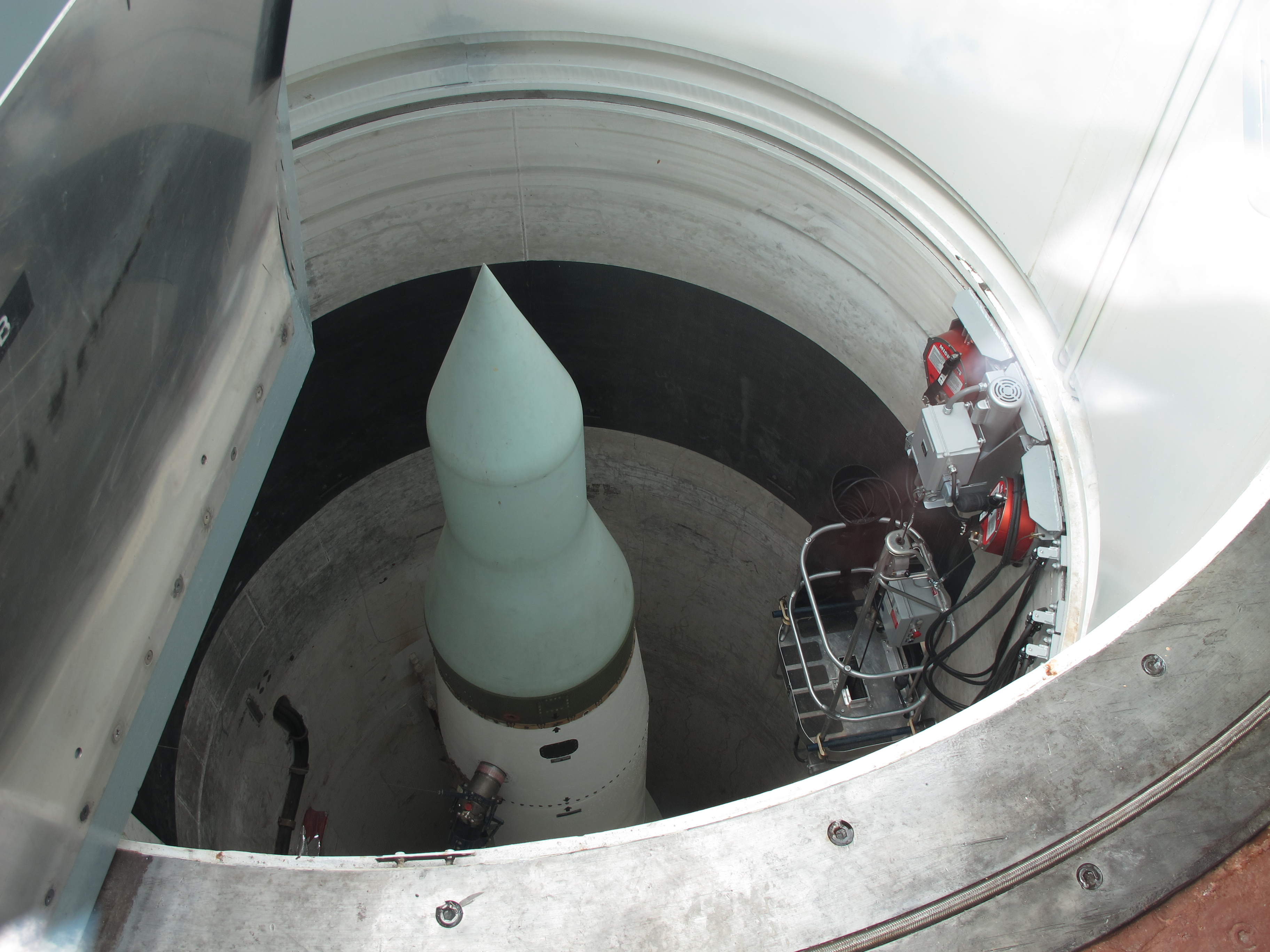
Decommissioned LGM-30F Minuteman II missile in its silo. The ERCS payload would have looked exactly like the mock fairing at the tip of the missile shown here. Source: Kelly Michaels, CC-BY-NC 2.0.
As was common with many Cold War projects, work on ERCS started before the launch vehicle it was intended for, the Minuteman II, was even constructed. As an interim solution, the Air Force mounted the payloads to their Blue Scout launch vehicles, a rocket that had only been used for satellites and scientific payloads. But it performed well enough in a series of tests through the end of 1963 that the Air Force certified the Blue Scout version of ERCS as operational and deployed it to three sites in Nebraska on mobile trailer launchers. The Blue Scout ERCS would serve until the Minuteman version was certified as operational in 1968, greatly improving readiness by putting the system in a hardened silo rather than in vulnerable above-ground launch trailers.
By the mid-70s, ten Minuteman II ERCS sorties were operational across ten different launch facilities at Whiteman Air Force Base in Missouri. Luckily, they and their spicier cousins all stayed in their silos through even the hottest days of the Cold War, only emerging in 1991 when the entire Minuteman II force was ordered to stand down by President George H.W. Bush. By that point, global military communications had advanced considerably, and the redundancy offered by ERCS was deemed no longer worth the expense of maintaining the 1960s technology that provided it. All ERCS payloads were removed from their missiles and deactivated by the end of 1991.